Back on the Road with K8GP Rover
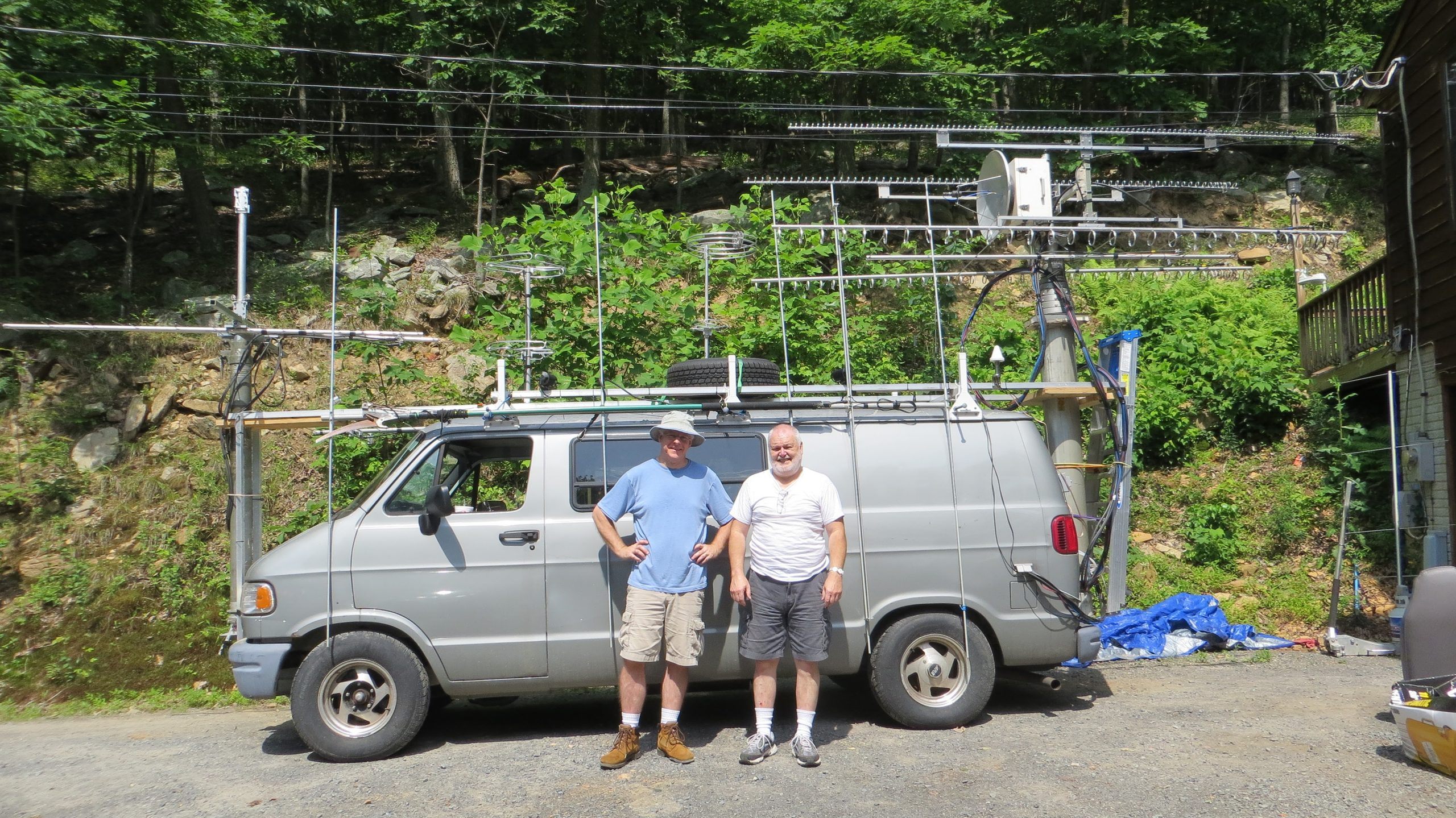
Andy K1RA & Terry W8ZN as K8GP/R in the ARRL September VHF Contest 2026
The K8GP Rover at the Directive Systems and Engineering workshop during final setup on September 11, 2026.

Terry W8ZN and I went into the 2026 ARRL September VHF Contest with modest expectations. We wanted to prove that the gray van, the antennas, the radios, and the two of us could still survive a full rover weekend. We were not trying to recreate our 2020 winning pace. We planned five familiar grids, sensible operating windows, and enough sleep to remain friends by Sunday night.
The weekend answered the basic question. We made 464 valid contacts on ten bands from 50 MHz through 10 GHz, activated five grids, and finished with a preliminary post-contest score of 91,045. We also hacked and bypassed a leaking heater core, drove through fog and rain with broken windshield wipers, straightened microwave loopers on a mountaintop, and replaced a 2.3 GHz antenna after a tree branch snapped it on the way down. In other words, it was a typical roving weekend!
| Valid QSOs | QSO points | Band grids | Activated grids | Preliminary score |
| 464 | 695 | 126 | 5 | 91,045 |
All operating times in this article are GMT. Distance figures are between the centers of the four-character Maidenhead grids and are therefore useful comparisons rather than surveyed path lengths. Grid maps are color coded using the resistor code where sequential band number 1=50 MHz=brown, 2=144 MHz=red, 3=222 MHz=orange, 4=432=yellow, etc. through 10=10 GHz=Gold. By default all band grids are overlaid and displayed at once, grouping 50-432 MHz on one map and 902-10368 MHz on another map. Use the slider icon to open a panel to toggle band visibility ON/OFF. Click a grid for a list of stations contacted.
You can listen to this article as an AI podcast overview by clicking https://rss.com/podcasts/back-on-the-road-with-k8gp-rover/ and clicking the play button next to S1 E1 57:25.
What We Were Trying to Do
The ARRL September VHF Contest runs from 1800 GMT Saturday through 0259 GMT Monday. The goal is to work as many stations and Maidenhead grid squares as possible on amateur bands above 50 MHz. Any legal mode may be used, and a station may be worked once per band, regardless of mode, from each rover grid visited.
September scoring gives one point for each 50 or 144 MHz contact, two points on 222 or 432 MHz, three points on 902 MHz or 1.2 GHz, and four points on 2.3 GHz and above. Each different grid worked on each band is a multiplier. A rover adds one more multiplier for every grid from which it completes a contact. Our analyzer therefore produced 695 QSO points times 131 multipliers, which is 126 band-grid multipliers plus 5 activated grids.
Official references ARRL September VHF page
| Band | September points per QSO | K8GP 2026 operating capability |
| 50 and 144 MHz | 1 | Both stations using shared RF systems |
| 222 and 432 MHz | 2 | Both stations using shared RF systems |
| 902 MHz and 1.2 GHz | 3 | Both stations separate RF systems |
| 2.3 GHz and above | 4 | Station #2 through 10 GHz only |
Team Intro
Terry W8ZN has been the lead on much of the K8GP RF hardware and antenna work over the years, along with being the owner (along with his wife Margie K4MEP) of Directive Systems & Engineering. The company manufactures specialized high-frequency, VHF, UHF, and microwave antennas, including the original antenna designs from Down East Microwave, Rutland Arrays (K1FO designs), Clarke Greene K1JX and custom microwave loop yagis. Terry was first licensed in January 1977 as WD8ISK (age 23) and has also held the call sign K8ISK before getting his current Extra Class call sign, W8ZN. He has been heavily active in VHF+ contesting since his early years in Ohio and has been active ever since in VHF-SHF bands, now up to 47 GHz, as well as Earth-Moon-Earth (EME/moon bounce) communication and VHF roving.
I will have been licensed for 50 years this December 2026. I started at age 12 as WB1ALW in Connecticut, became KA1GD after upgrading to Advanced in 1979, earned my Extra in 1980, and won the vanity call lottery for K1RA as my first-choice in 1996. VHF, UHF, and microwave contesting has been a common thread through most of my years on the air including as a single op in CT and along with the multi-op stations WB1FVS and W1VD in the 80’s. That led operating with the K1EA/K1TR BHVHFS team in PA in the 90’s and eventual K8GP Grid Pirates from WV & VA from 1994 onwards. Sprinkled along the way were stints with KC3WD, N3UW and W1RT as 2-man, multi-op rover teams. I always tried to bring additional engineering, hardware, software, construction and moral support over the years to the VHF+ contesting teams I have had the opportunity to participate with.
Multi-operator VHF+ work has a way of turning every project into a team effort. Someone has to design the controller, someone has to rebuild the yagi, and someone eventually has to remember where the special red crank was stored! And so it has been for the last least 3 decades for us.
Six Years Between Roves
Our last September rover effort together was in 2020. During the six years that followed, Terry moved Directive Systems and Engineering from Haymarket to a new workshop west of Winchester in FM09te. He kept working full time at BAE while building the shop, then recovered from a serious fall and another medical problem resulting in eye surgery. Terry and Margie K4MEP also designed and built a new home beside the workshop. We managed a few limited multi-operator contests from the shop, but a long rover weekend was off the table.
The gray van mostly sat in the field or driveway. Its pneumatic masts occasionally held a 6 meter or 2 meter array for a contest from the shop, so it never became completely ornamental. By late 2025, Terry had retired from BAE and recovered enough to start thinking about the road again. We agreed on a leisurely five-grid route and reused the station architecture that had worked before. The word leisurely became flexible almost immediately.
Earlier K8GP rover stories ARRL June VHF 2014 | ARRL June VHF 2016 and ARRL June VHF 2014 YouTube Video
Building the Rover Again
The weeks before the contest were less a restoration than an excavation. We removed microwave equipment from Terry’s fixed station, found the old VHF and UHF yagis, repaired elements and feed systems, and remounted pneumatic masts that had been taken off so the van could be inspected and licensed. Old rubber air hose and corroded power cables went into the discard pile. Terry acquired a nitrogen tank so we could refill the pneumatic system without continuing to buy small cylinders. Terry discovers after leaving both masts filled and extended, that the larger diameter, rear pneumatic mast has a slow leak and starts to collapse after an hour or so. It will have to do until we can rebuild it like we’d done with the front mast 10 years ago.
Power comes from a 12 volt, 1,200 amp-hour LiFePO4 battery box that Terry assembled from cells intended for his future home solar backup system. It weighs close to 200 pounds, which makes the word portable depend heavily on the van. A second 300 amp-hour battery joined the main pack to provide 24 volts for the rotors and Starlink Mini. We abandoned the first DC-to-DC converters after they produced roughly S9 noise across the bands. Quiet power mattered more than an elegant power diagram.
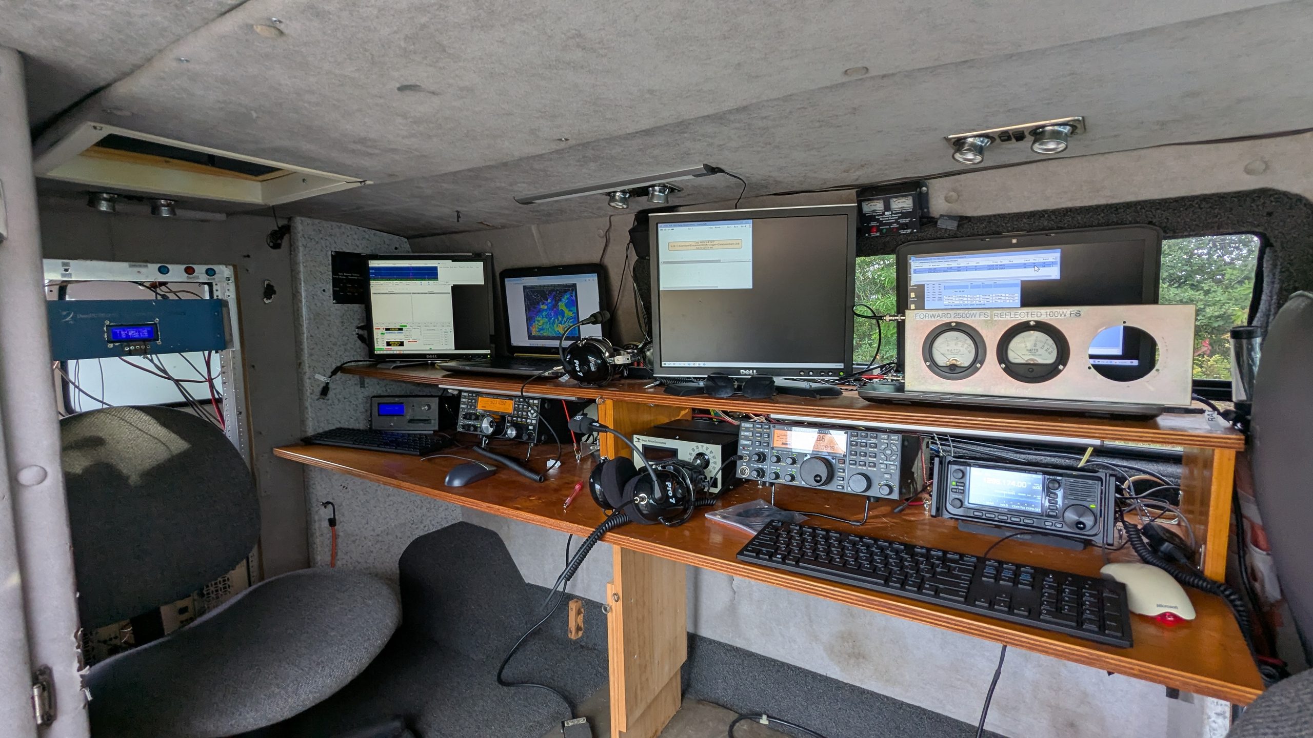
We reimaged two Intel i7 laptops and loaded Windows 10, N1MM Logger+, WSJT-X Improved, rotor control software, Chrome and Elecraft and Icom utilities. A crossover cable created the local station network, while Wi-Fi to the Starlink Mini provided Internet access. USB connections handled radio control, automated frequency tracking, logging, digital modes, CW, voice keying, and rotor control.
Two Stations Ten Bands
The rover carried two independent operating positions. I used Station 1 at the rear of the operating table for 50 through 1296 MHz. Terry used Station 2 at the front for 50 MHz through 10 GHz. Each position controlled its own pneumatic mast and rotor. Station 1 uses a smaller diameter 30 foot mast, a Yaesu 12 volt rotor, and a homebrew K3NG Arduino controller. Station 2 uses a larger diameter 40 foot mast, an M2 24 volt rotor, and a Green Heron controller.
Station 1 Operated by K1RA
| Band | Radio chain and output | Antenna |
| 50 MHz | Elecraft K3 at 20 W into TE amplifier at 200 W | DSEJX5-50 5 element yagi, 12 ft boom, 9 dBi |
| 144 MHz | K3 28 MHz IF into DEMI transverter and TE amplifier at 200 W | DSEFO144-12 12 element yagi, 17 ft boom, 14.5 dBi |
| 222 MHz | K3 27 MHz IF into DEMI transverter and TE amplifier at 100 W | DSEFO222-16 16 element yagi, 17 ft boom, 15 dBi |
| 432 MHz | K3 29 MHz IF into DEMI transverter and TE amplifier at 100 W | DSEFO432-25 25 element yagi, 17 ft boom, 18.5 dBi |
| 902 MHz | K3 145 MHz IF into mast-mounted SG Labs transverter at 3 W | DSE3311LYRM 11 element yagi, 3 ft boom, 14.5 dBi |
| 1.2 GHz | K3 146 MHz IF into mast-mounted SG Labs transverter at 2 W | DSE2314LYRM 14 element yagi, 3 ft boom, 15 dBi |
Station 2 Operated by W8ZN
| Band | Radio chain and output | Antenna |
| 50 MHz | Elecraft K3 at 50 W | Three-ring halo fixed to the roof rack |
| 144 MHz | K3 28 MHz I/F into DEMI transverter and TE amplifier at 200 W | DSE144-6RS 6 element yagi, 8 ft boom, 10.1 dBi |
| 222 MHz | K3 27 MHz I/F into DEMI transverter and TE amplifier at 100 W | DSEFO222-10RS 10 element yagi, 8 ft boom, 13.5 dBi |
| 432 MHz | K3 29 MHz I/F into DEMI transverter and TE amplifier at 100 W | DSEFO432-15RS 15 element yagi, 8 ft boom, 15.6 dBi |
| 902 MHz | Icom IC-905 145 MHz I/F into SG Labs transverter at 3 W | DSE3333LYK 33 element yagi, 12 ft boom, 18.5 dBi |
| 1.2 GHz | Icom IC-905 native at 10 W | DSE2345LYK 45 element yagi, 12 ft boom, 20 dBi |
| 2.3 GHz | Icom IC-905 native at 2 W | DSE1376LYK 76 element yagi, 12 ft boom, 23.4 dBi |
| 3.4 GHz | Icom IC-905 145 MHz I/F into DEMI transverter | DSE9112LYK 112 element yagi, 12 ft boom, 25 dBi |
| 5.7 GHz | Icom IC-905 native at 2 W | DSE dual-band feed and 60 cm dish, 28.3 dBi |
| 10 GHz | Icom IC-905 native at 0.5 W | DSE dual-band feed and 60 cm dish, 33.5 dBi |
The K8GP Rover Controller
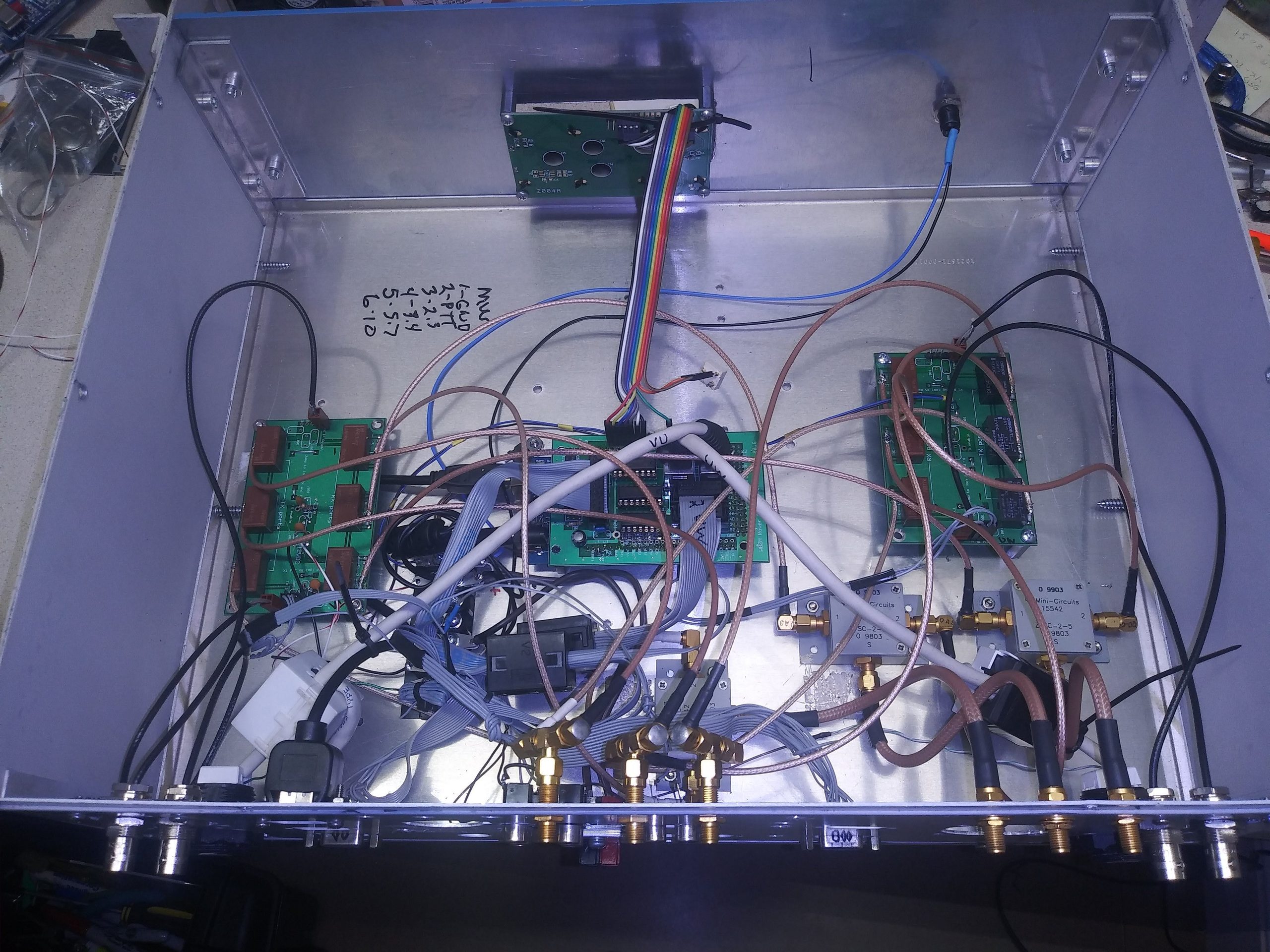
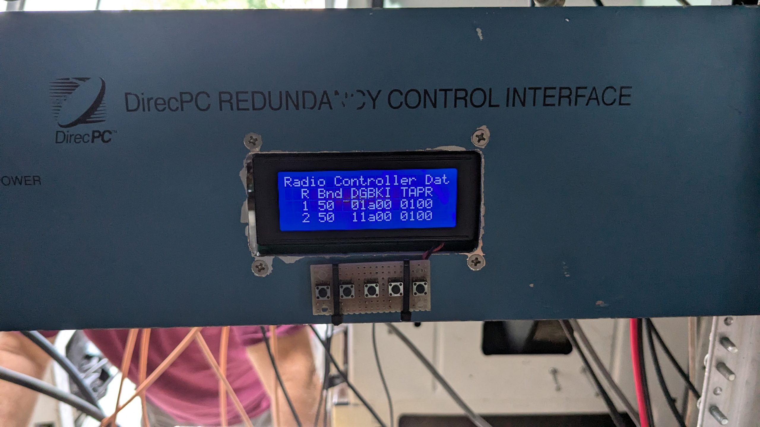
The two stations share the 144, 222, and 432 MHz transverters, amplifiers, and antennas through the K8GP Rover Controller. Terry designed the hardware around an Arduino Mega and shield, and I wrote the software. The controller watches BCD band data from both K3s, selects the proper 27 to 29 MHz I/F path and transverter with SMA relays, and lets both operators listen on the same band. The first station to transmit inhibits the other K3. Power dividers feed the two antennas on each shared band, allowing the operators to point in different directions at the cost of the splitter loss.
The system is a practical answer to a rover problem. Two operators can search different headings without duplicating complete high-power RF chains for three bands. It also creates a difficult RF environment. Six nearby VHF and UHF antennas, two receivers, shared high-power amplifiers, and short physical spacing leave little margin when one station transmits and the other tries to hear a weak signal. That weakness would follow us through the weekend.
Friday Night Reality Check
I arrived at Terry’s on Friday afternoon and was greeted with the first failure report. While building a Y-adapter to mix Elecraft K3 and IC-905 audio into one headset, Terry had apparently damaged the IC-905 headphone-output driver. The audio may use a floating ground, or the interconnection may have introduced voltage where none was welcome. For a while we also thought the K3 USB interface had failed. That problem proved to be the more traditional loose USB cable.
Before dark we connected antennas, exercised the pneumatic masts, and prepared for an on-air test with Dave K1RZ in FM19jh. A 50 MHz transmission locked up the IC-905, confirming that the two stations still had some local interference work ahead. Once we remotely helped Dave correct an audio feedback loop at his station, we ran from 50 MHz through 432 MHz testing. The rover controller and the shared 144, 222, and 432 MHz systems behaved correctly.
The 902 MHz and up tests produced another self-inflicted wound. An earlier firmware upgrade of his Icom 905 left Terry’s 902 MHz transverter exposed to 10 watts of drive from the Icom. Terry’s station could still receive, but transmit was gone. A spare transverter we found from a previous rover would receive but would not transmit. As we wound down, the batteries went on charge, the tools and spare parts went into the van, and we stopped around midnight local time with a one-station (Station #1) 902 MHz plan.
K8GP/R – Friday Eve – Picture Album
Click upper right corner of image to expand OR left or right edges of album to scroll
Contest Day 1 – Pennsylvania and the Weather
The first operating day was supposed to begin with an easy departure from FM09te, a two-hour drive to FN10, and plenty of setup time before the contest opened at 1800 GMT. We finally left the driveway at about 1445 GMT. Ten minutes down the hill, the smell of antifreeze arrived before the diagnosis. The heater core was leaking into the passenger footwell.
We turned around, let the engine cool, cut the heater hoses, bypassed the core, and left again around 1600 GMT. A Sheetz stop supplied gas and sandwiches. The lost time removed every bit of slack from the route, so our first contest decision happened before we even heard a signal. We would keep FN10 short and trim later stops as needed rather than turn the night into an endurance test.
K8GP/R – Day 1 Route – FN10-FM19-FN00
| Grid and site | Stop Letter | Elevation | Operating window GMT | Valid QSOs | Grid Op Time |
|---|---|---|---|---|---|
| FN10 Clarks Knob | B | 2,320 ft | 1832 to 2000 Sep 12 | 50 | 88 min |
| FM19 Big Mountain | C | 2,440 ft | 2122 to 2354 Sep 12 | 117 | 152 min |
| FN00 Sideling Hill | D | 2,280 ft | 0132 to 0234 Sep 13 | 43 | 62 min |
K8GP/R – Day 1 Morning – Picture Album
Click upper right corner of image to expand OR left or right edges of album to scroll
FN10db Clarks Knob
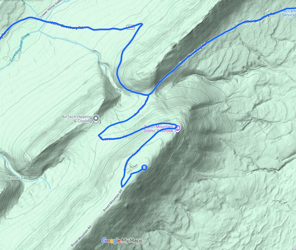
We reached the Clarks Knob area just before 1800 GMT and found a pickup truck and VHF antennas at the old commercial tower site just a stones throw from our setup spot. A honk of our horn and Jeff WN3A stepped out. Jeff and I had both operated with the Bird Hill VHF Society in the late 1990s and early 2000s, from K1EA / K1TR efforts from a ski area in FN20. The visit also closed another loop in rover history: Jeff had sold Terry our rover van years earlier and knew its original configuration and got some enjoyment still seeing it in operation.
We moved a few hundred feet down the road to the grassy opening at the fork, pointed the van north to establish the rotor calibration, and raised the arrays. Our first contact was NA1CN in FM19 on 50 MHz at 1832 GMT. Jeff was extremely loud from next door on every common band, so we tried to synchronize with his FT8 transmit periods or work elsewhere when he was active. The final logged contact was W3CMP/R in FM19 on 50 MHz at 2000 GMT.
The short stop produced 50 valid contacts and all 37 band-grid multipliers were new because it was our first rover location. The longest path was KV1J in FN44 on 144 MHz at about 412 miles. N9PGG in FM05 followed at about 362 miles on 144 MHz, while K1TR in FN42 was worked across 50, 144, 222, and 432 MHz at roughly 340 miles. K1RZ led the all-band partner list with nine contacts from this grid.
| Band | QSOs | Points | Grids | Best DX | DX grid | Miles |
| 50 | 7 | 7 | 5 | K1TR | FN42 | 339.8 |
| 144 | 24 | 24 | 16 | KV1J | FN44 | 411.9 |
| 222 | 5 | 10 | 5 | K1TR | FN42 | 339.8 |
| 432 | 7 | 14 | 5 | K1TR | FN42 | 339.8 |
| 902 | 1 | 3 | 1 | K1RZ | FM19 | 69.1 |
| 1.2G | 3 | 9 | 2 | K1RZ | FM19 | 69.1 |
| 2.3G | 1 | 4 | 1 | K1RZ | FM19 | 69.1 |
| 3.4G | 1 | 4 | 1 | K1RZ | FM19 | 69.1 |
| 5.7G | 1 | 4 | 1 | K1RZ | FM19 | 69.1 |
The opening stop did what we needed. It placed New England and Mid-Atlantic grids in the log quickly and confirmed that the basic station was functioning after the heater-core delay. Its 1.2 GHz and microwave contacts also showed that Terry could still build a useful high-band total despite the failed 902 MHz transmitter and lower power Icom 905 at his position.
K8GP/R – FN10db – Picture Album
Click upper right corner of image to expand OR left or right edges of album to scroll
K8GP/R – FN10 – Grids worked 50-432 MHz (Click Grid for QSO info)
Click upper left slider window icon to open panel to toggle MHz bands ON/OFF. Click upper right box to go full screen.
K8GP/R – FN10 – Grids worked 902 MHz – 10 GHz (Click Grid for QSO info)
Click upper left slider window icon to open panel to toggle MHz bands ON/OFF. Click upper right box to go full screen.
FM19aw Big Mountain
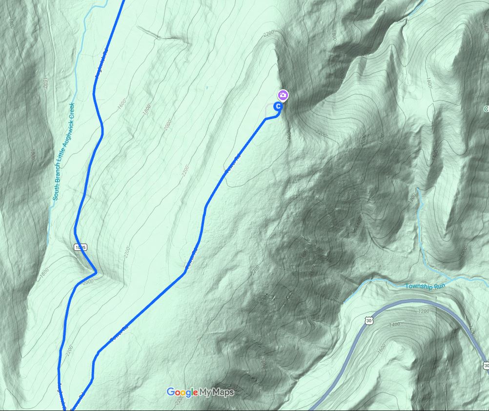
We left FN10 around 2015 GMT and followed a winding back road toward Big Mountain. We reached FM19aw about 2110 GMT. The sky was overcast and the ridge was starting to collect fog, but visibility remained good enough to set up without guessing where the mast was. N3EXA in FN20 went into the 50 MHz log at 2122 GMT, and WA3EKL in FM19 closed the stop on 50 MHz at 2354 GMT.
FM19 would be the best Day 1 location. We logged 117 valid contacts, 180 QSO points, and 33 new band-grid multipliers in 152 minutes. That is about 46 valid contacts per hour, the highest rate of the five stops we would make. Digital operation supplied 74 contacts, while phone added 36 and CW added 7.
The standout path was K4LY in EM85 on 144 MHz at about 430 miles. K1TR and AA1ON in FN42 supplied paths around 375 miles. At the high end, K1TEO in FN31 made the 3.4 GHz column at about 252 miles. K1RZ again led the grid’s all-band partner list with ten contacts, followed by W3IP with seven and K3TUF with six.
| Band | QSOs | Points | Grids | Best DX | DX grid | Miles |
| 50 | 38 | 38 | 18 | AA1ON | FN42 | 375.2 |
| 144 | 36 | 36 | 18 | K4LY | EM85 | 429.5 |
| 222 | 9 | 18 | 6 | K1TR | FN42 | 375.2 |
| 432 | 21 | 42 | 12 | K1TR | FN42 | 375.2 |
| 902 | 2 | 6 | 2 | K3TUF | FN10 | 69.1 |
| 1.2G | 4 | 12 | 3 | N3RG | FM29 | 106.7 |
| 2.3G | 2 | 8 | 1 | K1RZ | FM19 | 50.0 |
| 3.4G | 2 | 8 | 2 | K1TEO | FN31 | 251.5 |
| 5.7G | 1 | 4 | 1 | K1RZ | FM19 | 50.0 |
| 10G | 2 | 8 | 1 | K1RZ | FM19 | 50.0 |
By teardown, the fog had thickened and made us nearly blind on the descent down Tower Road, though conditions improved after we reached Route 30 and headed west. The radio path had been better than the visibility. That contrast would not survive the next stop.
K8GP/R – FM19aw – Picture Album
Click upper right corner of image to expand OR left or right edges of album to scroll
K8GP/R – FM19 – Grids worked 50-432 MHz (Click Grid for QSO info)
Click upper left slider window icon to open panel to toggle MHz bands ON/OFF. Click upper right box to go full screen.
K8GP/R – FM19 – Grids worked 902 MHz – 10 GHz (Click Grid for QSO info)
Click upper left slider window icon to open panel to toggle MHz bands ON/OFF. Click upper right box to go full screen.
FN00wa Sideling Hill
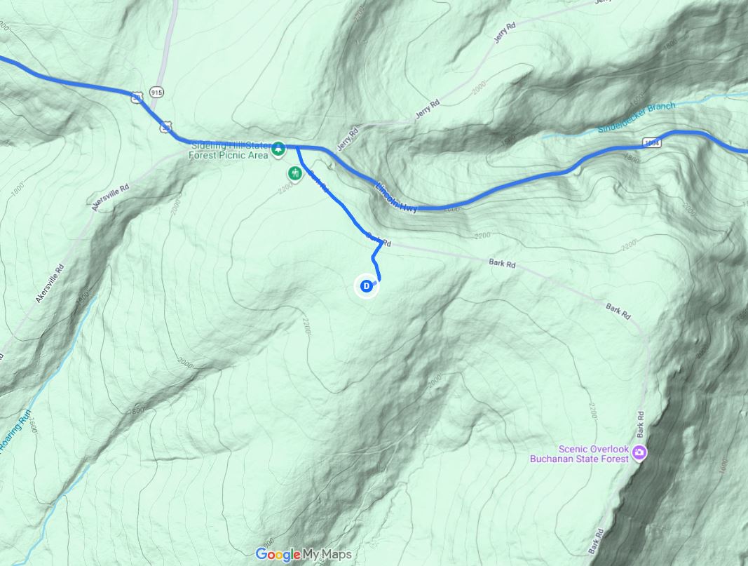
The approach to FN00wa became the difficult part of the night. Visibility fell again near Bark Road. At the site we could see only about 30 feet in the rain and fog, which made it surprisingly hard to orient a location we already knew. The antennas were finally up around 0126 GMT. K1TEO in FN31 was first at 0132 GMT on 50 MHz, and WN3A in FN10 was the last scoring contact at 0234 GMT on 432 MHz.
Signals were weak and microwave work was nearly absent. The van sat among wet pine trees and nearby towers. Antenna headings did not produce clean peaks, suggesting a messy combination of blockage, scattering, and reflections. We had no may to separate those effects on the spot, but the result was plain: 43 valid contacts, 59 points, and only 7 new band-grid multipliers.
The best paths still reached New England. K1TR on 144 MHz and WB1GQR on 50 MHz, both in FN42, were about 436 miles away. KE1LI in FN41 was about 423 miles on 50 MHz, and K4LY in EM85 reached about 408 miles on 144 MHz. Above 432 MHz, the stop produced only two 1.2 GHz contacts. K1RZ, K1TEO, and K3TUF tied as the most productive all-band partners with four contacts each.
| Band | QSOs | Points | Grids | Best DX | DX grid | Miles |
| 50 | 14 | 14 | 11 | WB1GQR | FN42 | 436.4 |
| 144 | 15 | 15 | 11 | K1TR | FN42 | 436.4 |
| 222 | 7 | 14 | 5 | K1TEO | FN31 | 320.4 |
| 432 | 5 | 10 | 4 | K1TEO | FN31 | 320.4 |
| 1.2G | 2 | 6 | 2 | W3IP | FM19 | 126.4 |
We voted not to visit the site again. That judgment combined the weak high-band performance, wet foliage, poor visibility, awkward setup, and the late hour. A famous site can still be the wrong site on a particular night.
K8GP/R – FN00wa – Picture Album
Click upper right corner of image to expand OR left or right edges of album to scroll
K8GP/R – FN00 – Grids worked 50-432 MHz (Click Grid for QSO info)
Click upper left slider window icon to open panel to toggle MHz bands ON/OFF. Click upper right box to go full screen.
K8GP/R – FN00 – Grids worked 902 MHz – 10 GHz (Click Grid for QSO info)
Click upper left slider window icon to open panel to toggle MHz bands ON/OFF. Click upper right box to go full screen.
The Trip Home (Day 1 Ends)
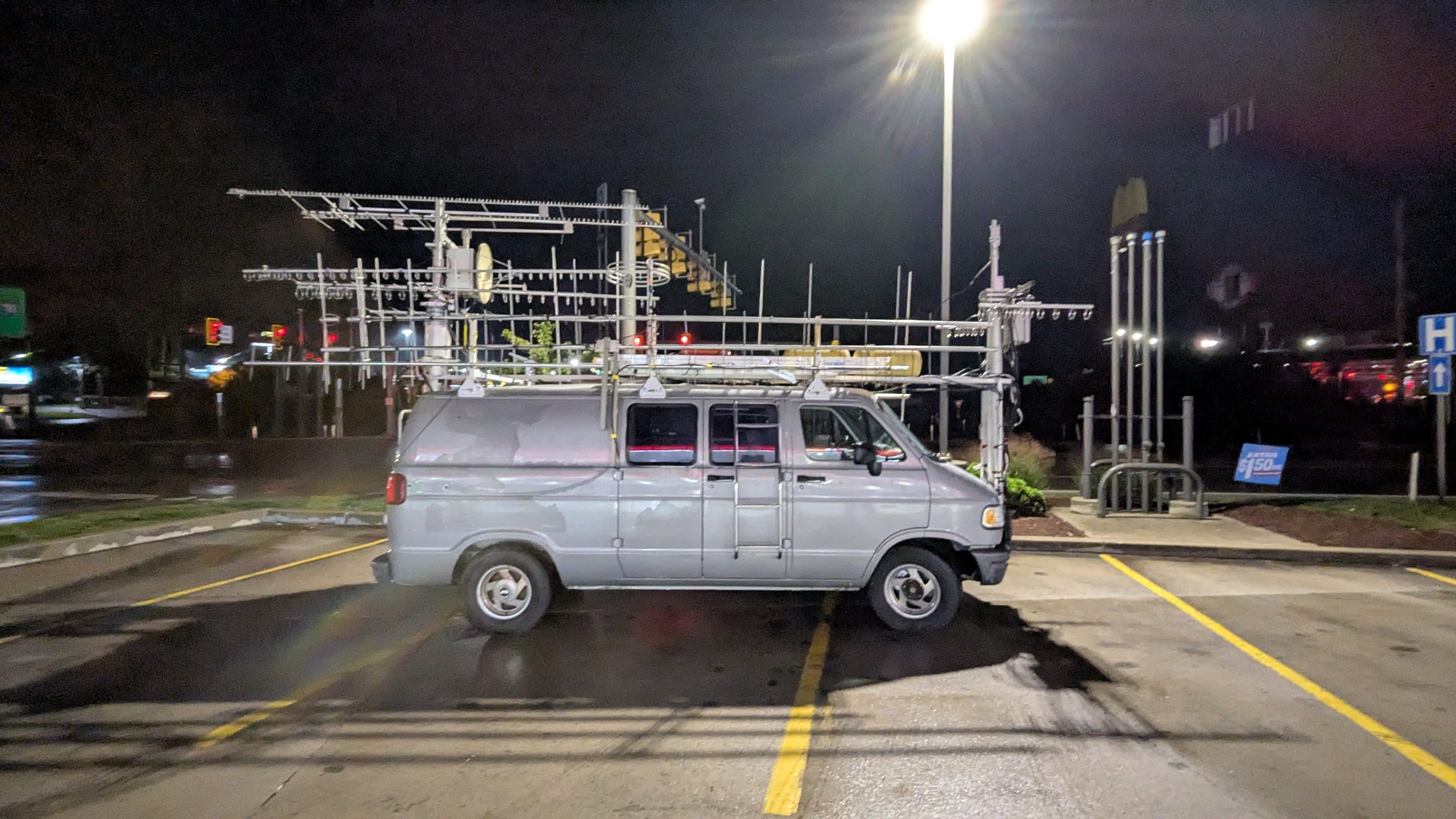
We collapsed the masts and packed the front antennas on the roof in the rain. After 0300 GMT we stopped at Sheetz in Breezewood for fuel, food, and a short reset. The rain lightened, and then the windshield-wiper linkage broke with the blades halfway through a sweep. Radar suggested that the heavier rain would miss our route. It did, and a few sprinkles were manageable without functional wipers. We reached FM09te around 0445 GMT, connected the batteries to the chargers, and planned to be awake again at 0945 GMT.
Regional station archives recorded light rain and mist around south-central Pennsylvania during this part of the weekend, consistent with what we saw on the ridges. The weather mattered directly to setup and travel. It also left wet foliage around FN00, an obvious loss mechanism on the microwave bands. It is tempting to assign every signal change to propagation, but site blockage and wet trees were enough to explain much of FN00’s poor performance.
K8GP Rover Pit Stop at the Sheetz in Breezewood, PA ~0300Z
Contest Day 2 – Reddish Knob and Home
The van was covered in dew on Sunday morning. Margie K4MEP found us a squeegee and paper towels because the failed wipers had removed the easy solution. We left around 1100 GMT and stopped several times until airflow and sunlight finally cleared the windshield. The route down Interstate 81 turned pleasant as the sky opened, but the last climb to Reddish Knob brought the fog back.
K8GP/R – Day 2 Morning – Picture Album
Click upper right corner of image to expand OR left or right edges of album to scroll
K8GP/R – Day 2 Route – FM08-FM09
| Grid and site | Stop Letter | Elevation | Operating window GMT | Valid QSOs | Grid time |
|---|---|---|---|---|---|
| FM08 Reddish Knob | B | 4,397 ft | 1346 to 1844 Sep 13 | 159 | 298 min |
| FM09 Shawneeland | C | 2,420 ft | 2300 Sep 13 to 0106 Sep 14 | 95 | 126 min |
FM08jl Reddish Knob
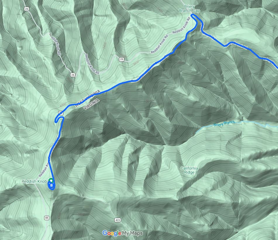
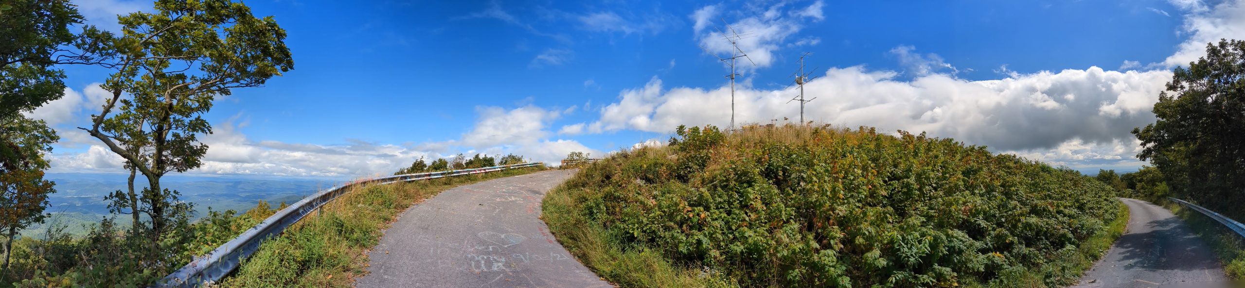
Low branches on the gravel approach tested the rear microwave array before we reached the summit. At the top we found bent loops on the 2.3 and 3.4 GHz yagis. I climbed onto the roof and worked the loops back into shape while the only other person on the summit documented our deployment technique with his camera. Apparently our antics offered him some amusement. Terry notes that the nitrogen tank is almost empty, so we’ll cut it close to getting the two masts to fully extend. Will they last the planned, longer operating stay?
We made the first contact with N2NT in FN20 on 50 MHz at 1346 GMT. The pre-contest Hepburn forecast had suggested possible enhancement from before sunrise through about midday local time. We arrived late for the predicted window, but FM08 was still the productive grid of the weekend. The raw log ended at 1844 GMT with a repeat 5.7 GHz contact to K1RZ. The final scoring contact was K1RZ on 10 GHz at 1843 GMT.
FM08 produced 159 valid contacts, 238 QSO points, 95 band-grid combinations at the site, and 43 multipliers that were new to the weekend. The longest path was WV4P in EM55 on 50 MHz at about 589 miles. On 222 MHz we reached K1WHS in FN43 at about 541 miles. K1KG and W1XM in FN42 were about 503 miles away on 144 MHz, and N4SV in EN61 made a 432 MHz path of about 471 miles.
The higher bands also did real work. We completed seven 1.2 GHz contacts in six grids, three 2.3 GHz contacts, two 3.4 GHz contacts, one 5.7 GHz contact, and two 10 GHz contacts. K1RZ led the all-band list with ten contacts. K3TUF and W3IP followed with seven each, while K1TEO and N3RG had five each.
| Band | QSOs | Points | Grids | Best DX | DX grid | Miles |
| 50 | 56 | 56 | 29 | WV4P | EM55 | 589.2 |
| 144 | 48 | 48 | 26 | K1KG | FN42 | 502.8 |
| 222 | 17 | 34 | 13 | K1WHS | FN43 | 541.3 |
| 432 | 22 | 44 | 14 | N4SV | EN61 | 471.3 |
| 902 | 1 | 3 | 1 | K1RZ | FM19 | 127.7 |
| 1.2G | 7 | 21 | 6 | K1TEO | FN31 | 379.2 |
| 2.3G | 3 | 12 | 2 | K3TUF | FN10 | 174.6 |
| 3.4G | 2 | 8 | 2 | K3TUF | FN10 | 174.6 |
| 5.7G | 1 | 4 | 1 | K1RZ | FM19 | 127.7 |
| 10G | 2 | 8 | 1 | W3IP | FM19 | 127.7 |
K8GP/R – FM08 – Grids worked 50-432 MHz (Click Grid for QSO info)
Click upper left slider window icon to open panel to toggle MHz bands ON/OFF. Click upper right box to go full screen.
K8GP/R – FM08 – Grids worked 902 MHz – 10 GHz (Click Grid for QSO info)
Click upper left slider window icon to open panel to toggle MHz bands ON/OFF. Click upper right box to go full screen.
I watched DXMaps.com over the day, but it only indicates MUF, not the actual propagation mechanism for the 50 MHz paths. A 589 mile FT8 contact could involve short sporadic E, meteor enhancement, tropospheric bending, or a combination. I found no public archive that proves a broad Mid-Atlantic sporadic-E opening during our operating window, so the safe conclusion is that Reddish Knob, better conditions, and nearly five hours of operating gave us the best low-band reach and the largest multiplier harvest.
K8GP/R – FM08 – Picture Album
Click upper right corner of image to expand OR left or right edges of album to scroll
The Trip Home and A Tree Collects the 2.3 GHz Antenna
Upon packing up and leaving the site and near the bottom of the mountain on the return drive we heard a pop and a snap. There was no safe place to stop, so we continued until the road widened. A branch had broken the rear of the 2.3 GHz looper and left it hanging from the feedline. The impact also bent the H-frame mounting bolts, pointing the whole microwave array about ten degrees toward the ground. We still had a two-hour drive to FM09 and no useful repair option beside the road.
Back at the shop, I climbed the ladder while Terry searched the rafters for parts or spares. He emerged with an identical antenna. Having a rover partner who owns an antenna company occasionally improves the spare-parts situation! We removed the broken looper, salvaged the feedline, installed the replacement, and moved the van from the workshop driveway to the higher house driveway.
Click upper right corner of image to expand OR left or right edges of album to scroll
FM09te Shawneeland
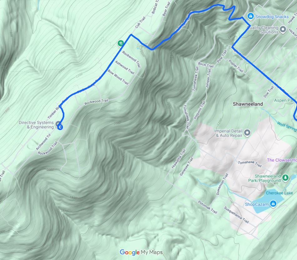
The repaired rover returned to the air at 2300 GMT with N2NT in FN20 on 50 MHz. We were tired from the short night, the driving, the mountain setup, and the roadside-style microwave repair performed in a driveway. The original plan had us operating to the contest close at 0259 GMT. We agreed instead to give the last grid a useful run and stop while it was still fun.
Conditions were fair but clearly below FM08. New England was harder, and most of the remaining high-band work depended on coordination with familiar stations. We made 95 valid contacts and 139 points in 126 minutes. Only six band-grid multipliers were new, which is normal for a final grid after the earlier stops had already filled much of the multiplier table.
W2SZ in FN32 was the longest path on both 50 and 144 MHz at about 375 miles. N4JP in FM14 reached about 363 miles on 144 MHz, and VE3PJ in FN14 was about 360 miles on 50 MHz. K1RZ again led the all-band partner count with nine contacts, followed by W3IP with seven and K1TEO with five. AD4TJ in FM08 closed the log on 50 MHz at 0106 GMT.
| Band | QSOs | Points | Grids | Best DX | DX grid | Miles |
| 50 | 36 | 36 | 15 | W2SZ | FN32 | 375.2 |
| 144 | 29 | 29 | 17 | W2SZ | FN32 | 375.2 |
| 222 | 10 | 20 | 8 | K1TEO | FN31 | 344.2 |
| 432 | 11 | 22 | 8 | K1TEO | FN31 | 344.2 |
| 902 | 1 | 3 | 1 | K1RZ | FM19 | 76.0 |
| 1.2G | 3 | 9 | 2 | K1TEO | FN31 | 344.2 |
| 2.3G | 2 | 8 | 1 | W3IP | FM19 | 76.0 |
| 3.4G | 1 | 4 | 1 | K1RZ | FM19 | 76.0 |
| 5.7G | 1 | 4 | 1 | K1RZ | FM19 | 76.0 |
| 10G | 1 | 4 | 1 | W3IP | FM19 | 76.0 |
The last grid completed the weekend rather than transforming it. FM09 added only 834 new-grid points when viewed in isolation, but its 95 contacts and high-band runs contributed to the 695-point base that multiplied every band grid we had accumulated. We shut down almost two hours before the contest ended, dropped the masts, and left the detailed interference testing for Terry to perform in daylight later in the week after he recovered.
Click upper right corner of image to expand OR left or right edges of album to scroll
K8GP/R – FM09 – Grids worked 50-432 MHz (Click Grid for QSO info)
Click upper left slider window icon to open panel to toggle MHz bands ON/OFF. Click upper right box to go full screen.
K8GP/R – FM09 – Grids worked 902 MHz – 10 GHz (Click Grid for QSO info)
Click upper left slider window icon to open panel to toggle MHz bands ON/OFF. Click upper right box to go full screen.
The Weekend in Numbers
A Python log-analysis application I developed removed 14 repeat contacts from the 478 QSO lines in the Cabrillo file, leaving 464 valid contacts. It then produced the band, grid, mode, top-station, and KML map files used throughout this article. The scoring resulted in 695 QSO points times (126 worked + 5 visited) 131 grid multipliers for 91,045 points.
Grid Performance
FM08 supplied the largest volume and the most new multipliers because we stayed there for nearly five hours and the site opened useful paths in several directions. FM19 had the fastest valid-QSO rate at about 46 per hour. FN00 was the clear weak link: its 43 contacts added only seven new band grids, and the microwave columns stopped at 1.2 GHz. The 726 minutes between first and last contacts at the five sites total 12 hours and 6 minutes of operating time.
K8GP/R Cumulative Running Point Score After Operating Each Grid
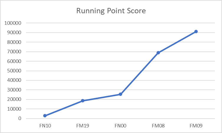
Cumulative Running Point Score After Operating Each Grid and Operating Time per Grid
| Grid | QSOs | QSO points | New band grids | Running score | Minutes |
| FN10 | 50 | 79 | 37 | 2,923 | 88 |
| FM19 | 117 | 180 | 33 | 18,648 | 152 |
| FN00 | 43 | 59 | 7 | 25,440 | 62 |
| FM08 | 159 | 238 | 43 | 68,944 | 298 |
| FM09 | 95 | 139 | 6 | 91,045 | 126 |
| Total (5) | 464 | 695 | 126 | 91,045 | 726 |
Band Results for Entire Contest
The two one-point bands carried the contact total. We made 151 contacts on 50 MHz and 152 on 144 MHz, nearly identical volumes. The 144 MHz log was slightly more concentrated geographically, with 35 grids compared with 38 on 50 MHz. The 222 and 432 MHz systems added 114 contacts but 228 QSO points because each contact was worth two. Above 432 MHz, only 47 contacts produced 150 points, showing why even a small number of microwave contacts matters.
| Band | QSOs | QSO points | Unique grids | Band score |
| 50 | 151 | 151 | 38 | 5,738 |
| 144 | 152 | 152 | 35 | 5,320 |
| 222 | 48 | 96 | 16 | 1,536 |
| 432 | 66 | 132 | 21 | 2,772 |
| 902 | 5 | 15 | 2 | 30 |
| 1.2G | 19 | 57 | 7 | 399 |
| 2.3G | 8 | 32 | 2 | 64 |
| 3.4G | 6 | 24 | 3 | 72 |
| 5.7G | 4 | 16 | 1 | 16 |
| 10G | 5 | 20 | 1 | 20 |
K8GP/R Grids worked 50-432 MHz – All Contest (Click Grid for QSO info)
Click upper left slider window icon to open panel to toggle MHz bands ON/OFF. Click upper right box to go full screen.
K8GP/R Grids worked 902 MHz – 10 GHz – All Contest (Click Grid for QSO info)
Click upper left slider window icon to open panel to toggle MHz bands ON/OFF. Click upper right box to go full screen.
Modes and Operating Style per Band for Entire Contest
Digital modes accounted for 286 contacts, or 61.6 percent of the valid log. Voice supplied 141 contacts, or 30.4 percent, and CW supplied 37, or 8.0 percent. The distribution changed with frequency. Digital dominated 50 and 144 MHz, while 222 MHz and above increasingly depended on direct voice or CW coordination. No digital contacts appear above 432 MHz in the log.
| Band | Voice | Morse | Digital |
| 50 | 27 | 2 | 122 |
| 144 | 31 | 6 | 115 |
| 222 | 29 | 5 | 14 |
| 432 | 27 | 4 | 35 |
| 902 | 4 | 1 | 0 |
| 1.2G | 10 | 9 | 0 |
| 2.3G | 5 | 3 | 0 |
| 3.4G | 4 | 2 | 0 |
| 5.7G | 2 | 2 | 0 |
| 10G | 2 | 3 | 0 |
| TOTAL | 141 | 37 | 286 |
The Stations We Kept Finding the Entire Contest
K1RZ was the weekend’s anchor station with 42 unique contacts, including 22 on 902 MHz and above. K3TUF and W3IP tied for second overall with 25. Their totals came from different strengths: K3TUF had 19 contacts on 50 through 432 MHz and six higher, while W3IP had 14 lower-band contacts and 11 at 902 MHz and above. K1TEO, N3RG, N2NT, and AA4ZZ supplied important depth across the route.
The per-grid Top 3 files show the same pattern. K1RZ led or tied the lead from every grid and completed nine or ten bands from four of the five locations. W3IP became especially important on the microwave bands from FM19, FM08, and FM09. At FN00, where conditions and site loss suppressed the high bands, the leaderboard compressed into lower-band ties instead of long microwave runs.
| Band group | Rank | Call signs | Unique QSOs |
| All bands | 1 | K1RZ | 42 |
| All bands | 2 | K3TUF W3IP | 25 |
| All bands | 3 | K1TEO | 18 |
| All bands | 4 | N3RG | 17 |
| All bands | 5 | N2NT | 16 |
| 50 through 432 MHz | 1 | K1RZ | 20 |
| 50 through 432 MHz | 2 | K3TUF | 19 |
| 50 through 432 MHz | 3 | N2NT | 16 |
| 50 through 432 MHz | 4 | K1TEO N3RG | 15 |
| 50 through 432 MHz | 5 | AA4ZZ W3IP | 14 |
| 902 MHz and up | 1 | K1RZ | 22 |
| 902 MHz and up | 2 | W3IP | 11 |
| 902 MHz and up | 3 | K3TUF | 6 |
| 902 MHz and up | 4 | K1TEO | 3 |
| 902 MHz and up | 5 | N3RG | 2 |
Comparing 2026 with Recent Septembers
The supplied ARRL result comparison covers leading Classic Rover scores from 2020 through 2025. Our preliminary 91,045 would have won the category in 2021, 2022, and 2024, and would have placed second in 2020, 2023, and 2025. Among the supplied results, it is the fourth-highest score, behind our own 2020 K8GP result, VE3OIL/R in 2023, and VE3OIL/R in 2025.
| Year | Rank | Call | Score | QSOs | Grids or multipliers |
| 2020 | 1 | K8GP/R | 198,488 | 768 | 172 |
| 2020 | 2 | N7GP/R | 79,918 | 645 | 62 |
| 2021 | 1 | K9PW/R | 74,694 | 279 | 118 |
| 2022 | 1 | K2QO/R | 73,188 | 392 | 107 |
| 2022 | 2 | VE3OIL/R | 72,688 | 338 | 118 |
| 2023 | 1 | VE3OIL/R | 97,966 | 348 | 146 |
| 2023 | 2 | K2QO/R | 78,516 | 392 | 108 |
| 2023 | 3 | KF2MR/R | 73,341 | 373 | 87 |
| 2024 | 1 | VE3OIL/R | 77,625 | 336 | 125 |
| 2025 | 1 | VE3OIL/R | 93,470 | 355 | 130 |
| 2026 | Preliminary | K8GP/R | 91,045 | 464 | 131 |
The comparison also shows why a raw QSO count is not enough to judge a rover score. The 2026 effort logged fewer contacts than our 2020 run, but it remained competitive with recent winners because ten-band contacts raised the point base and 131 total multipliers kept the score moving. The 2020 result remains in another class by itself: 768 contacts, 172 reported grids or multipliers, and 198,488 points. I guess that’s what being younger and having more stamina produces!
What Worked and What Needs Work
The Systems That Earned Their Keep
The main LiFePO4 pack, auxiliary battery, pneumatic system, rotors, laptops, logging network, Starlink link, and K8GP Rover Controller supported the full weekend. Though as we exhausted the nitrogen tank at FM08, we used an electric air compressor to fill the masts at FM09. The shared-band logic behaved correctly during testing and contest operation. The quick-release antenna hardware kept ordinary setup and teardown manageable, which mattered after the late starts and bad weather.
The choice to remove noisy DC-to-DC converters was correct. An S9 self-generated noise source would have erased the benefit of the high sites. The two-station architecture also let one operator search lower bands while the other pursued coordinated microwave runs. K1RZ’s 22 high-band contacts and W3IP’s 11 show what that capability contributed.
The Problems That Followed Us
Interstation interference on 144, 222, and 432 MHz was the largest radio problem. External receive filters helped, but the close antenna spacing and split arrays still overloaded the opposite station during high-power transmission. Before another serious rove, we need measured isolation data for every transmit and receive combination, better sequencing where needed, and a review of filter placement, relay isolation, grounding, and cable routing.
The IC-905 also needs attention. The headphone-output failure, the 50 MHz RF lockup, and the 902 MHz overdrive incident all reduced confidence in the Station 2 chain. The 902 MHz spare that received but would not transmit needs bench diagnosis. Drive-level limits should be enforced in hardware or configuration so a firmware reset cannot expose a low-level transverter input to ten watts.
Mechanical protection is the other clear lesson. The fixed rear H-frame is efficient once parked but vulnerable on narrow wooded roads. The bent loopers and broken 2.3 GHz antenna were warnings. We need a travel-height check, more branch clearance, a stronger or sacrificial mounting scheme, and a departure checklist that includes the position of every element, feedline, and frame. The heater core and wiper linkage belong on the same pre-trip mechanical list even though neither is an RF component.
Would We Do It Again
By the drive back from Reddish Knob, Terry and I were already discussing January. We had also rediscovered the parts of roving that six years could not erase: the small burst of relief when the first station answers from a new grid, the satisfaction of moving a contact through ten bands, the strange calm inside a van while rain and fog turn the mountaintop outside into a different world, the point at which the skies clear and you can see for miles and miles and the running technical conversation that continues between sites.
We did not match the 2020 result, and that was never the real test. We returned the K8GP rover to the road, worked ten bands from five grids, produced a score that compares well with recent Classic Rover leaders, and reached the end still talking about improvements. The gray van is no longer an alternate antenna support. It is a rover again!
Data and Source Notes
The contest analysis in this article comes from the supplied Cabrillo log and CSV, KML, and KMZ files generated by Andy K1RA’s Python log-analysis application. The application groups contacts by band and operated grid, removes repeat contacts for scoring, computes points and grid multipliers, ranks frequently worked stations, and builds coverage maps whose popups contain the worked grid, calls, QSO count, and grid-center distance.
The five per-grid packages contain consistent band summaries, grid scoring, Top 3 station rankings, and band-specific KML maps. The EntireContest package supplies the Cabrillo log, overall band and mode summaries, Top 10 station rankings, complete band maps, and two route KMZ files. The historical comparison comes from Sept VHF top scores 2020-2025.xlsx derived from the Top ARRL VHF Scores – https://contests.arrl.org/scores.php
Other related information derived from: